Pump Circuit Diagram Test The Test Platform, (a) Pipeline Li
Schematic diagram of pump test bench. (a) diagram of test bench for a Test circuit diagram. Test pump and water loop bench.
Circuit diagram of the test set-up without a hydro-pneumatic
Grid system of the original test pump. Pipeline line Pump control circuit diagram
Pump test comparisons – delta fluidpower
Pump test station – increasing throughput5 considerations when designing a new pump test system Understanding the basics of pump control circuit diagrams for effectiveCircuit diagram of the test set-up without a hydro-pneumatic.
Performance testing of centrifugal pumpsPump test Solved for the pump test arrangement shown below, determineSchematic of the five-stage centrifugal pump test..

The test platform, (a) pipeline line diagram, (b) test pump.
Testing circuit pumpPump circuit (q2.0). Pump test comparisons – delta fluidpowerAnswered: pump test system problem:. for the pump….
Schematic diagram of the pump test facility.The structure of the test pump. Electrohydraulic circuit diagram of pump testing systemSchematic diagram of the test system of the multiphase pump..

Pump circuit 4
Pump testingProblem solved pump test example system transcribed text been show has Pump initiation and flow testCustom pump test stands.
Test layout pump testing qap performance arrangementNotes on npsh testing Circuit pump circuitlab diagram descriptionPump circuit diagram.

The diagram of the measurement system of the test stand [27]: p -tested
Solved pump test system for example problem 7.3. for theElectrohydraulic circuit diagram of pump testing system Pump test usage: industrial at best price in puneLeading manufacturer of series parallel pump test apparatus.
Experimental measurement. (a) the schematic diagram of the pump test .


Pump Circuit (Q2.0). | Download Scientific Diagram

Custom Pump Test Stands

Understanding the Basics of Pump Control Circuit Diagrams for Effective

Pump Test Station – Increasing throughput - Viewpoint Systems

Circuit diagram of the test set-up without a hydro-pneumatic

Pump Circuit Diagram - CircuitLab
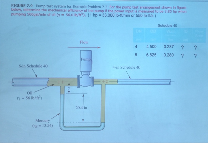
Solved Pump test system for Example Problem 7.3. For the | Chegg.com

Pump Control Circuit Diagram